|
|
 Back to Home-page |

Voor NL versie klik hier
Photo of the antenna
Click on the drawing for a larger version Click on the drawing for a larger version
Click on a photo for a larger version
Photo 1: A piece of 5/8 "PVC pipe is pushed over the bottom cable section (heat up the PVC pipe with a paint burner and then slide over the cable)
Note that the rest of the antenna is reinforced with a wooden plant stick of 8mm. Stuck here with pastic tape.
Photo 2: 2 holes are drilled: 1 of 7 mm for the upper ground connection (red) and 1 of 9 mm for the inner conductor + lower ground (green / yellow).
Photo 3: The bottom mass is first soldered on the cable shield (red), and the red wire is cut at 1 cm. The inner veins are folded against each other.
Photo 4: The short piece of cable is temporarily glued or secured with a wire. The inner veins are soldered together.
Photo 5: Pass the previously soldered lower ground wire through the hole (yellow / green).
Photo 6: Place the BNC chassis connector in place with the central pin against the inner vein (s). Solder the center pin of the BNC and then the ground wire.
Photo 7: Setup in the garden at 6 m height. For long-term installation outdoors, a 3/4 "PVC pipe can be pushed over with a sealing cap at the top.
Click on a photo for a larger version
Photo 1: The antenna is made out of one piece (1230 cm) of 75 ohm TV cable. The complete whole is shown here.
Photo 2: The coiled take-out antenna.
Photo 3: Detail of STUB end: the inner vein is jointly soldered together on the outside.
Photo 4: The inner conductor of the STUB is soldered to the inner conductor of the cable through a hole in the cable.
Beware: the mass must not be touched.
Photo 5: A 75 ohm TV antenna connector can also be used for connection.
Note: Only 1 ferrite bead has been transferred at the STUB. This may be 3 or more eg from old PC power supplies) . Or you can wind the cable 6 windings arround the tube .
Click on a photo for a larger version
Photo 1: The antenna up to the connector is a piece of 50 ohm network cable. The whole is shown in 1 whole.
Photo 2: Rolled up antenna to take with you. At the top is a small eye folded to be able to hang the antenna with a string.
Photo 3: For indoor installation there is a piece of PVC tube of 5/8 "partly slid over the BNC chassis.
The whole is mounted on a metal box with a coupling BNC -> PL259 and a counter PL259 chassis.
Photo 4: Detail of the STUB to the BNC chassis connector. The 2 middle conductors go together to the middle pin of the BNC. The 2 masses together to the BNC.
Photo 5: Arrangement in the attic - preferably at a window.
Click on a photo for a larger version
Photo 1: The antenna up to the connector is made of 50 ohm or 75 ohm cable. The upper whole is only partially shown.
Photo 2: Display overview STUB and 3 usable ferrite beads (eg from old PC Power supply).
Photo 3: Detail of fitting STUB on the cable with an electrical capstone. Note that the inner conductor of the STUB is twisted with mass.
Photo 4: Detail of 3 ferrite beads to be used. This may all be the same types.
Photo 5: A 75 ohm TV antenna connector can also be used to connect the cable to a receiver.
A picture of the reception of this antenna
Downloads: dl8kdl.net_PA0FBK antenna demystified.pdf
http://www.qsl.net/pa0fbk/hampage_uk.htm#coax
 mail: on1bes Scarlet.be
Test and construction of the FBK 2/70 'Mystery' antenna
A travel, or a fixed vertical coax antenna (origin PA0FBK).
Design
This antenna is very easy to make from a piece of 50 ohm or 75 ohm coaxial cable, and can be either smooth (roll-up version) or rigid cable. The costs are practically zero if it is made from surpluses of RG-58 (50 ohm cable). This is also the former network cable, remember, from that time with the BNC T-pieces.
This antenna is considered by some as somewhat "mysterious" because the operation is open to discussion. Nevertheless, the performance of this antenna is very good, and it peaks, with the specified lengths on at least 2 bands: 2 m and 70 cm. With different dimensions the antenna can be made for other frequencies. But to receive only, all intermediate frequencies are also well received, starting from +/- 100Mhz to 600MHz or even higher to a good 1GHz, with some attenuation.Townsman principle (single band)
 |
In principle, the FBK 2-70 antenna is a derivative of the old "Townsman" antenna (sleeve antenna), and it also looks a bit like the J-Pole antenna. The operation of the Townsman is not discussed here but you can look up with Google. The principle also occurs in the FBK 2-70 antenna.
PA0FBK vertical coax antenne (dual band)

|

|
Click on the drawing for a larger version
I have built several types of this antenna, both with flexible and rigid coax .You need 1 piece cable lenght of 1230cm.
A flexible version is ideal as a travel antenna (in a tree, hanging out of a window, etc.). A fixed version for home use .
A BNC or PL259 connector below the antenna, can be used for the feed point, but you can also leave the cable intact. What is necessary, however, is a decoupling for shield currents at the feeding point where the BNC is otherwise, just below the STUB. This can be done in two ways: with thin cable, 6 turns of the power cable can be rolled up like a coil on a plastic tube of 4 to 5 cm. Or sliding 3 to 5 ferrite cores across the cable . For thick cable, a number of larger ferrite ring cores can be slide over the cable at the of the feed point (at least 3 pieces). You can also install 4 radials at the feed point, just below the STUB. Placing the antenna with a PL259 or BNC on a base plate is a good thing, but is not strictly necessary.
Afterwards, tape the antenna with adhesive tape or crimping PVC tube.
Take a good look at the photos of the FBK2 / 70: for each version, the cable length of 1230cm are the same.
This antenna also works reasonably indoors, but stay away from computers and power supplies, and the best place is in the vicinity of a window. In this case, the antenna can be mounted on a metal base plate or box with a gradient connector.
In principle, the antenna can also be used outdoors. However, he is not independent enough to stand in the wind. It is necessary for all versions that a plastic (electrical) tube is pushed over the antenna, and that the tube at the top is made watertight with a cap, and that at the bottom the connections with heat shrink and tape are completely sealed.
A little bit of theory:
The theory is not necessary for this antenna to work, so those who can not wait and immediately want to start,
can safely skip this and start building.
The basic principle of this antenna is based on an (old) Townsman antenna. We consider this as a 1/2 wave antenna.
An ingenious system is provided here to connect an antenna element (tube) with the correct impedance (alternating current resistance)
to the end of a 1/2 wave element. A half-wave element is high-ohmic (+/- 2000 ohms) on one endpoint,
and our antenna cable is low-ohmic (if coaxial cable = 50 ohms), so we can not connect that without a transformation
of the impedance from low to high. Simply a half wave element can easily be connected by adding a 1/4 wavelength element to it.
This then reduces the input impedance to about 270 ohms. Normally we could only connect the antenna with a symmetrical
cable (300 ohms). For example the former 300 ohm "ribbon" TV cable. Nowadays only coax cable of 50 or 75 ohm is available,
so that an adjustment is still required. This is done by means of the small piece of cable (the "Stub").
The length of this piece of wire is determined on which a 50 or 75 ohm point can be found electrically.
The Stub also allows us to connect a coax cable directly instead of the (outdated) symetric ribbon cable.
For 50 ohms that piece of wire in the Townsman is about 75 mm long. The FBK2-70 uses both the inside and the outside
of a piece of coax as a guide, so this piece is about 35 mm long. This is not all that critical for reception.
If we were to transmit with this antenna and power would start on it, and the right 50 ohm point should be accurately determined.
The FBK2 / 70 is in its basic form a 2-meter half-wave antenna, and will behave like that, in the middle of the 2m band (145MHz). The half wave element for 2m will be in resonance only and at exactly this frequency. The radiation pattern is then the same as every 2m vertical half wave antenna, or also like a 2m J-pole antenna. Seen as a 2m half wave antenna, the piece of undamaged cable jacket in the middle does not really play a role.
If we look at the antenna as a 70cm antenna (435MHz), it will be completely different. Here, the piece with an unremovared plastic cover does resonate at about 435MHz. The 2m half wave element is then divided into 3, and the upper and lower part will also resonate at 70cm. These are then each half a wave at 70cm. In this way we get in principle a duo-band antenna. Now the antenna is similar to a dual band Open-Sleeve antenna.
But in practical terms, a few things are wrong. Firstly, the piece with the plastic cable jacket is in resonance on the 70cm band, but it is actually not connected, and as a half wave element is quite far removed from the feed point. It does form a sort of capacitive coupling between the upper and lower element. As a result, the good radiation properties of this element are largely lost. However, according to measurements, this piece of cable is necessary for this antenna to work at 70cm. If we had to feed this piece of cable in the middle, the profit would have been maximal.
Secondly, in measurements with simulation programs (MMANA), the radiation angle for 70 cm rises by 20 to 25 degrees. This gives the disadvantage that this antenna may not be set too high in the air. For some, of course, an advantage. A max. Height of 6 to 10 meters is recommended here.
For local use and both fixed and movable, this has proved to be a good antenna. The gain should be between 3 to 5 dB, depending on the materials used. The (VNA) measurements show that there are several peaks where a terminating resistance of 50 ohms is approached between 100MHz and 600MHz. But for single reception this is not that important.
VNA Measurements:
Click on the drawing for a larger version
This graph is for the 50 ohm RG58 cable (in a PVC tube). You will see 5 peaks where a certain resonance occurs. Of which 2 peaks: 1 on the 2m band and 1 on the 70cm band that closely approach the 50 ohm terminating resistor. This certainly does not mean that there is no reception between the peaks. This concerns the measured terminating resistance, and not the measured reception strength. Above 500 MHz, reception is still possible up to ADSR on 1095 MHz.
Different versions
Note: if you can solder, this one is for you, if not, read on.
Look carefully to the foto's of the FBK 2/70 : on each version, the same cable lenght of 1230cm is used.Version 1:
Design with thick rigid 75 ohm cable with PL259 connector:
1. Antenna with the decoupled PVC sections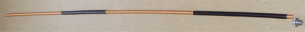
2. Antenna with removed copper sections 
|
5. Indoor arrangement on a metal base

|
7. Outdoor installation on a mast of 6 m

|
3. Detail of the Stub (or hair-pin - a piece of single copper wire)

|
||
4. Detail of the hairpin - a piece of 3/4 PVC tube

|
6. Detail PL connector and a metal base plate

|
Photo 1: A piece of 5/8 "PVC pipe is pushed over the bottom cable section (heat up the PVC pipe with a paint burner and then slide over the cable)
Note that the rest of the antenna is reinforced with a wooden plant stick of 8mm. Stuck here with pastic tape.
Photo 2: 2 holes are drilled: 1 of 7 mm for the upper ground connection (red) and 1 of 9 mm for the inner conductor + lower ground (green / yellow).
Photo 3: The bottom mass is first soldered on the cable shield (red), and the red wire is cut at 1 cm. The inner veins are folded against each other.
Photo 4: The short piece of cable is temporarily glued or secured with a wire. The inner veins are soldered together.
Photo 5: Pass the previously soldered lower ground wire through the hole (yellow / green).
Photo 6: Place the BNC chassis connector in place with the central pin against the inner vein (s). Solder the center pin of the BNC and then the ground wire.
Photo 7: Setup in the garden at 6 m height. For long-term installation outdoors, a 3/4 "PVC pipe can be pushed over with a sealing cap at the top.
Version 2:
Version with thin RG-59 (75 Ohm) TV cable in one piece, as a travel antenna or as a fixed antenna:
1. The antenna is made of one piece of 1230 cm cable
|
|
2. Rolled up travel antenna 
|
3. Detail of the coax stub
|
4. Detail of the stub soldering
|
5. A normal TV 75 ohm coaxial plug

|
Photo 1: The antenna is made out of one piece (1230 cm) of 75 ohm TV cable. The complete whole is shown here.
Photo 2: The coiled take-out antenna.
Photo 3: Detail of STUB end: the inner vein is jointly soldered together on the outside.
Photo 4: The inner conductor of the STUB is soldered to the inner conductor of the cable through a hole in the cable.
Beware: the mass must not be touched.
Photo 5: A 75 ohm TV antenna connector can also be used for connection.
Note: Only 1 ferrite bead has been transferred at the STUB. This may be 3 or more eg from old PC power supplies) . Or you can wind the cable 6 windings arround the tube .
Version 3
A version with thin RG58 50 ohm network cable and BNC connector, as travel antenna or fixed antenna (in a tube):
1. Antenna from one piece of cable

|
5. Attic placement
|
|
2. Rolled up antenna for on the go
|
3. Antenna foot detail in a 5/8 PVC tube 
|
|
4. Detail of the coax stub and BNC connector 
|
||
Photo 1: The antenna up to the connector is a piece of 50 ohm network cable. The whole is shown in 1 whole.
Photo 2: Rolled up antenna to take with you. At the top is a small eye folded to be able to hang the antenna with a string.
Photo 3: For indoor installation there is a piece of PVC tube of 5/8 "partly slid over the BNC chassis.
The whole is mounted on a metal box with a coupling BNC -> PL259 and a counter PL259 chassis.
Photo 4: Detail of the STUB to the BNC chassis connector. The 2 middle conductors go together to the middle pin of the BNC. The 2 masses together to the BNC.
Photo 5: Arrangement in the attic - preferably at a window.
Version 4
Look carefully to the foto's of the FBK 2/70 : on each version, the same cable lenght of 1230cm is used. This antenna can be built by everyone. It is even possible to use completely 75 ohm material from the electro shop (TV cable, plugs) so that a soldering iron is not required for the construction.Antenna WITHOUT SOLDERING with thin RG58 or RG59 cable
1. Antenna from one piece of cable
|
|
2. Detail of the coax stub (is a small piece 35mm coax)

|
3. Detail of the stub assembly
|
4. Possible to use Ferrite beads

|
5. A normal TV coax connetor to end
|
Photo 1: The antenna up to the connector is made of 50 ohm or 75 ohm cable. The upper whole is only partially shown.
Photo 2: Display overview STUB and 3 usable ferrite beads (eg from old PC Power supply).
Photo 3: Detail of fitting STUB on the cable with an electrical capstone. Note that the inner conductor of the STUB is twisted with mass.
Photo 4: Detail of 3 ferrite beads to be used. This may all be the same types.
Photo 5: A 75 ohm TV antenna connector can also be used to connect the cable to a receiver.
This version is made as a travel antenna, and there is no need to solder!
A picture of the reception of this antenna

Reception on the 2m band. Note that there are practically no recurring smooth lines (interference of PC, power supply, LCD, internal crystal ...). Real signals are clearly visible in the waterfall.
Links :Downloads: dl8kdl.net_PA0FBK antenna demystified.pdf
http://www.qsl.net/pa0fbk/hampage_uk.htm#coax
mail: on1bes Scarlet.be